The engine governor controls engine speed, and in some generator applications, generator load. To select correct governors for particular applications, governor capabilities must be understood. The following terms are commonly encountered when describing governors:
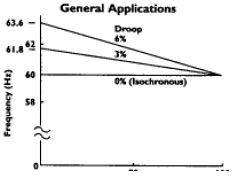
Droop, Speed Droop and Regulation are terms used interchangeably to describe the relationship of engine speed change from no load (high idle) to full load (rated) in steady state operation. Expressed as a percentage, droop is calculated using the equation below.
![]()
 The graph at right illustrates various degrees of droop for both generator and industrial engine applications. Percent droop remains constant and independent of operator speed change. If the operator changes the throttle on an industrial engine, he or she is actually changing the full load speed. The full load rpm would shift either up or down. The percent increase in speed to no load speed would remain the same.
Many applications easily accept some speed droop which means a less costly and complex governor can be used, even if the gen set will be paralleled with other units.
Isochronous – These units offer 0 percent droop – constant engine speed from no load to full load. This capability is often required in applications demanding precise frequency control such as communications equipment, computers, movie lighting, clocks and automatic paralleling applications.
Compensation – This is the feed back adjustment that tunes the governor to the application for stable engine operation. Hydraulically or electrically actuated governors are available, although they are more costly.
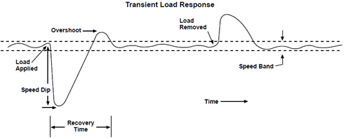
Speed Band – The above graph shows the tolerance on speed at any steady load. It can be different for different engine/governor combinations.
Transient Response – This is the time interval required for engine speed to recover from a sudden load change. Overshoot is the maximum monetary increase in frequency on sudden load removal. The transient response graph below shows how an engine reacts to sudden load changes.

Generator Set Stability and Response
The transient response and steady state stability of generator set engines can vary because of a number of factors: engine model, engine speed, aspiration, power factor, governor and the presence of an idle circuit.
Diesel engines have a short mechanical path between the governor actuator and the fuel delivery system to the combustion chamber. This system responds quickly to load change request from the governor.
ISO Class 1 and 2 are international standards for generator set response criteria. The two different ISO Classes refer to the performance level or specifications. Class 2 has more demanding performance specifications than Class 1. The following table reflects the current ISO standards for Class 1 and 2 diesel engines.
Transient Response
| Class 2 | Class 1 | |
|---|---|---|
| Frequency recovery time | 5 sec | 10 sec |
| Frequency deviation | +20% | +25% |
| Tolerance for recovery | 2.0% | 3.5% |
| Voltage recovery time | 6 sec | 10 sec |
| Voltage deviation @0.8 power factor | +25% | +30% |
| Tolerance for recovery | +2.2% | +2.8% |
Note: This criteria is based on adding load in three steps:
Step 1 116 psi bmep
Step 2 117 psi to 196 bmep
Step 3 197 psi to 261 bmep
Steady-State Stability
| Class 2 | Class 1 | |
|---|---|---|
| Frequency | 1.5% | 2.5% |
| Voltage | 2.5% | 5.0% |
